Here is an idea for electronic version of the pulse generator. The pulse generator uses blocks that wear down with time increasing the dwell. There is anecdotal evidence that when the dwell increases the engine runs richer, assumed to be contact bounce generating additional injector pulses. An electronic version would solve this problem and create a non-mechanical solution.
Electronics need power so the first problem is how to power them. The four pulse generator signals are supplied with 5V from the ECU through a pull-up resistor. When a contact closes the pulse generator pulls the signal down to ground.
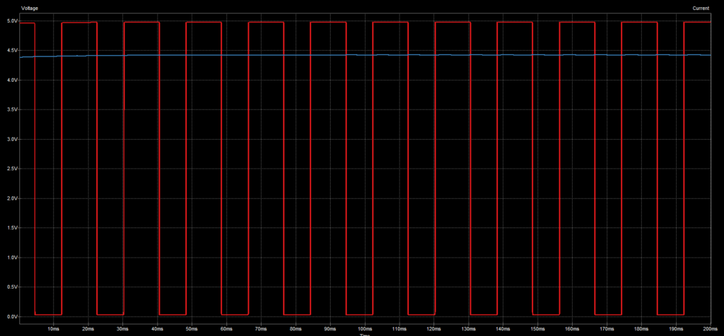
Looking at the four signals there is always at least one that is at 5V. If we logically OR the signals together we can get a constant 5V, however we don’t want to interfere with the pulses. Diodes solve this with the trade off of a voltage drop.
The red waveform is the E13 output from the EPG. The blue waveform is 4.4V that can be passed to an LDO 3.3V regulator. I’ve used a large capacitor to smooth it instead for the purposes of this demonstration.
Here is the circuit diagram.
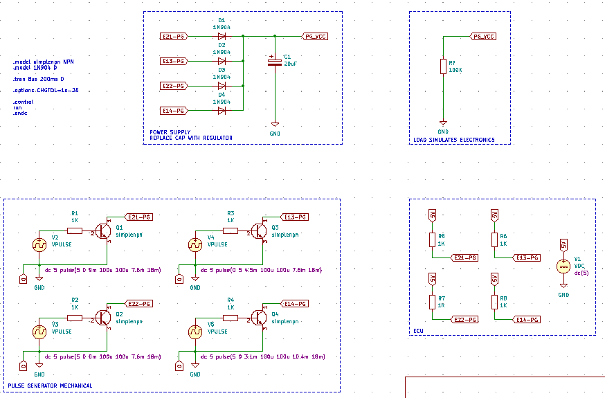
This diagram shows everything needed to perform the simulation in KiCAD 6.
An analysis in the simulation by adding a load shows that at least 80mA can be sunk by an electronic pulse generator without affecting the operation of the ECU. This should be plenty for a microcontroller, LED and some discrete components.
Comments are closed