Because all four signals have a known, fixed relationship to each other, we just need to know when one of the two cams on the distributor shaft get to a known point when a mechanical contact would have been closed. Once we have that edge on a signal we can calculate and generate all of the waveforms from it.
To do this we can use a hall effect sensor with a magnet placed in front of it (credit to The Benzo Man on the Benzworld forums for this idea). However the output from the sensor only varies from 0V to 0.2V, has noise and relatively slow rise and fall times.
We could feed this signal into an ADC on a microcontroller and process it there, but it is much better to pass it through a signal conditioning circuit instead to create a nice clean 3.3V waveform that is easily processed.
Here is an example hall effect sensor waveform with a lot of noise, generated by circuit simulation.
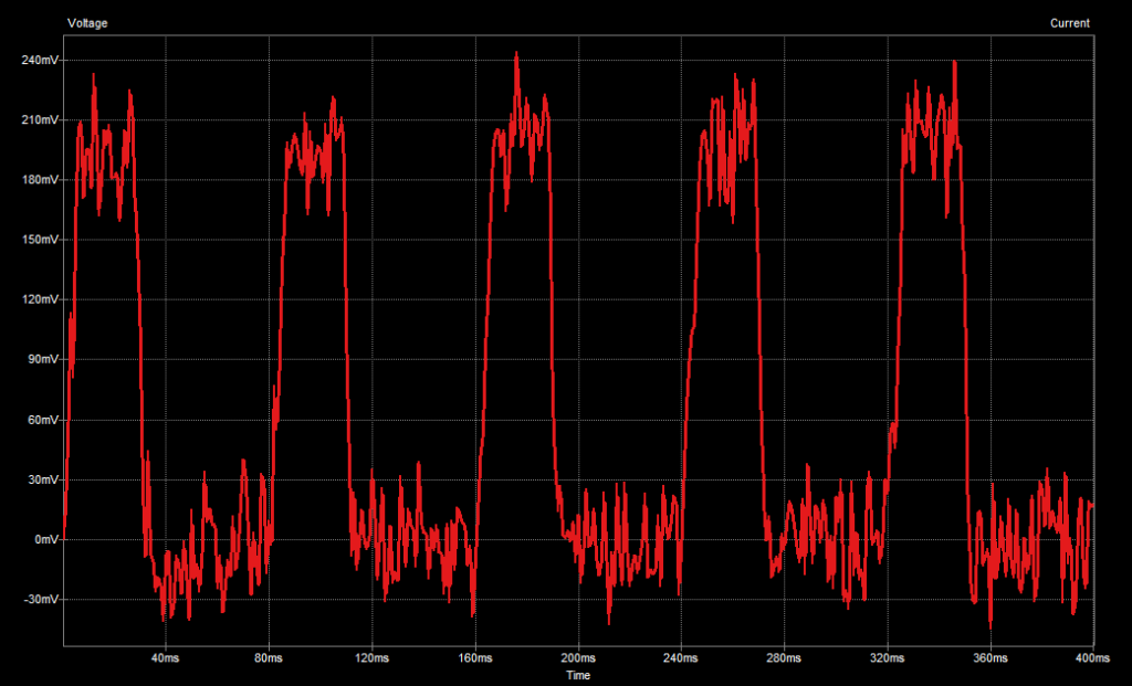
This is fed into a low pass filter to reduce the noise and then into a comparator. When the waveform crosses a reference voltage of 0.1V the output goes up to 3.3V.
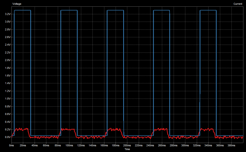
This produces a 3.3V square wave that can be fed into a digital input pin with edge triggering interrupts enabled. No need for ADC or DMA complexity.
However the issue is the slow fall time. Here is a close up of the relationship between the fall time and the output falling edge.

Reducing the reference voltage will make the falling edge later relative to the hall effect waveform but at the risk of false edges appearing. Likewise it can be shifted earlier by increasing the reference voltage.
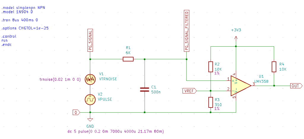
Here is the circuit. The signal conditioning can be placed right next to the sensor to reduce any additional noise.
Comments are closed